Description
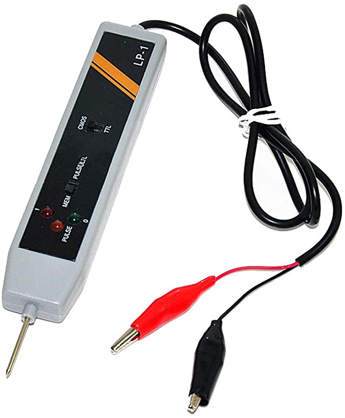
The GLP-1A logic pulse can be used to perform in-circuit testing of TTL, CMOS, and many other logic devices at a maximum of 50MHz. The GLP-1A is enhanced with a logic probe function with a minimum detectable pulse width of 10 ns, providing enough sensitivity for most applications.
How to use:
- Connect RED clip to + terminal and BLACK clip to – terminal of the power source of the circuit under test.
- For TTL and DTL, set the upper select switch to the side marked “TIL”
- For CMOS, set the upper select switch to the side marked “CMOS”, contact the probe pin to the point to be tested. The LEDs will indicate its logic states: A) ALL LEDs OFF -High impedance B) RED LED ON – High State (1) C) Green LED ON – low State (0) D) Orange LED ON – Pulse.
- For detecting and storing pulse or level transition, set lower select switch to side marked “PULSE” first. Contact the probe pin to the point to be tested. The LEDs will indicate is basic state. Then set the lower select switch to side marked “MEM”, The orange LED will light when any pulse or level transition is detected. The pulse direction, in comparison with the original basic, state, cable determined. After use, reset logic probe by setting the lower select switch back to side marked “PULSE”
Features:
- Handy, Quick and Easy
- Supply: 3-18 VDC
- For: DTL, TTL and CMOS
- High Frequency Response
- Instant Indication
- Pulse Memory Function
Specification:
- For TTL/CMOS/DTL
- 4 states detectable/LO/Pulse/Hi-Impedance
- Maximum input frequency20MHz
- Pulse Memory Function
- Reverse Power Polarity Protection
- Supply: 3-18 VDC
Package Includes:
1 x LP-1 DTL TTL CMOS Pulse Memory Logic Tester Probe.


Reviews
There are no reviews yet.